Radio stations around 12MHz could not be received because of interference of CPU clock.
Bar antenna for AM(350u~450uH) is required to receive MW1 and MW2 band.
c)Clock accuracy
30s per month
d)Others
Speaker can be driven directry with onboard NJM386D speaker driver IC.
Printed circuit board size 3.95"(W)×2.56"(D)×1.97"(H).
2.Movie
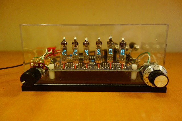
a)Introduction of VFD tube clock with AM, FM, ShortWave Radio kit "DSP-2"
b)Detailed receiving test movie of AM band and FM band.
c)Detailed receiving test movie of Short wave band.
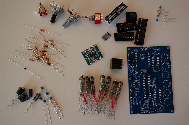
3.Included parts of the kit
a)Please prepare DC12V power supply (AC adapter etc) separately.
b)Bar antenna for AM(350u~450uH) is required to receive MW1 and MW2 band.
For more details, see the assembling manual.
5.Circuit overview
This circuit has 2 types power sources 12V DC and 3.3V DC.
3.3V DC is supplied to CPU and DSP radio module.
12V DC is supplied to VFD and audio amplifier IC.
3.3V DC is generated with onboard voltage regulator IC.
DSP radio module is controlled by CPU via I2C interface.
VFD are driven at 12V DC with transistor array IC controlled with CPU.
For more information, please refer schematic above.
This circuit has 2 switches. Toggle type and push type.
Toggle type switch is used for three purposes.
First purpose is to switch radio function to clock function.
2nd one is to cut DC12V supply for audio amplifier IC NJM386
in order to stop residual noise when clock mode.
3rd one is to store frequency data of all band and time information to EEPROM inside CPU.
These data are stored when toggle switch is turned on or off.
Push button also has 3 functions.
First function is to switch band when radio mode.
2nd one is to adjust clock when clock mode.
3rd one is to clear EEPROM.
EEPROM data is erased when push the button and connect power cable(AC adapter etc) to this kit at same time.
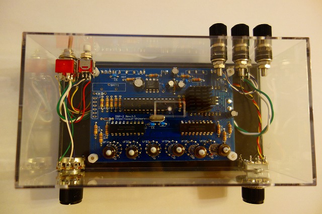
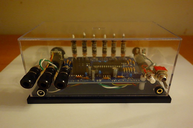
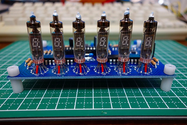
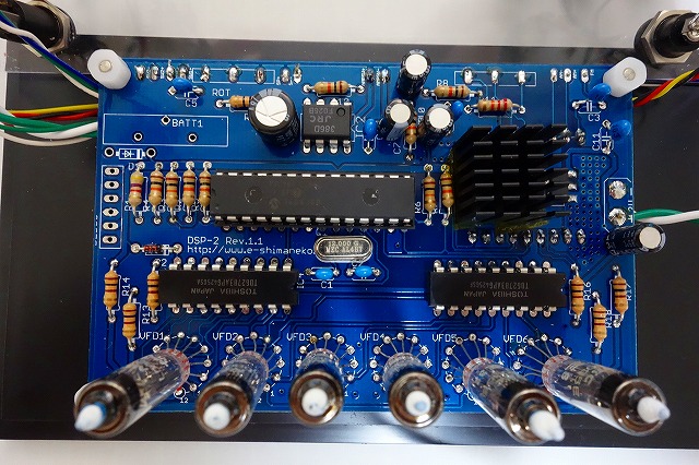
6.Assembling sample
#Chassis, switch knobs, terminals and spacers are not included in this kit.